InnoTrans 2026 · Berlin · 22-25 September · Hall 17, Booth 425
- €185 B Global rail market 2024-25
- €34 B Power-electronics investment 2025-30 (CAGR 6.3%)
- 70 % New platforms with SiC (2026)
- + 40 years in railway power electronics
1. Market in Transition: Three Converging Vectors
The global rail market stands at €185 billion per year (2024-25), with a projected 4% CAGR to 2030. Three vectors explain the structural shift: mass electrification — more than 60% of new acquisitions are electric or hybrid, with Europe leading at an 85% electrified network; end-to-end vehicle digitalization — digital twins, IoT predictive maintenance and smart energy management; and reconfiguration of onboard power electronics toward wide-bandgap and distributed modular architectures.
The specific railway power-electronics sub-segment is valued at €11.2 billion globally, with a 6.3% CAGR — clearly above the growth of the parent market. Cumulative investment projected for 2025-2030 reaches €34 billion, with traction converters capturing 58% and auxiliary systems (HVAC, passenger services, chargers) growing rapidly on the back of existing-fleet renewal. Technical specification is converging globally toward EN 50155 as the reference, even in Asia-Pacific and North American markets that traditionally operated under alternative regulatory frameworks.
2. Technology Vectors: SiC, MMC, Distribution and Bidirectionality
Four simultaneous technology leaps are redefining what a railway power-electronics platform must deliver. Each addresses a specific limitation of the previous generation, and all raise the engineering demands placed on the supplier.
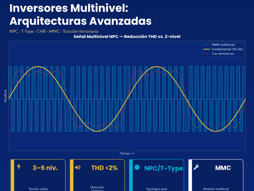
SiC as the default semiconductor. Silicon Carbide adoption moves from selective to mainstream: projections indicate SiC will be specified in ~70% of new platforms in 2025-2026. The technical case is built on four simultaneous improvements over silicon IGBT: 97-98% efficiency vs. 92-94%; 30-40% mass reduction through lower thermal dissipation and more compact passives; switching frequencies up to 100 kHz vs. 2-5 kHz for IGBT (70% reduction in inductors and filters); and 175-200 °C operating Tj vs. 125 °C for silicon.
Modular Multilevel Converters (MMC). In high-power traction (6-9 MW) the MMC topology is consolidating as the dominant architecture: 70% reduction in harmonics injected into the catenary, power factor > 0.98, lower stress through voltage distribution across modules. The 25% initial cost premium is amortized through lower maintenance and longer service life. The implication for auxiliary design is indirect but significant: the MMC architecture modifies the catenary’s harmonic spectrum, requiring recalibrated EMC immunity in the auxiliary converters that share that bus.
Distributed architectures. Migration from centralized 200+ kVA systems toward networks of distributed 10-15 kVA inverters per zone. The advantages are operational: fault isolation without affecting the full service, granular per-zone monitoring, optimal sizing to actual load, modular replacement without immobilization. Benefits reported across fleets: 40% cabling reduction and reliability improvement above 35%.
Bidirectionality and digital twins (2027-2030 horizon). Bidirectional converters with energy return to the catenary (regenerative efficiency > 85%) and integration with smart grids for auxiliary services will move from pilot to standard in 2027-2028. In parallel, digital twins with ML for predictive maintenance are reaching fault-detection accuracies of 90-95% with windows of up to 90 days, becoming widespread toward 2029-2030. Platforms acquired in 2026 will operate until 2056: firmware-extensibility toward these capabilities is a selection criterion today.
3. Design Implication: From Compliance to Durability
Adopting SiC, MMC or modular distribution is not a bill-of-materials decision — it is an engineering-process decision. The dominant failure modes in railway power electronics — electrolytic capacitor degradation, electromechanical wear, thermo-mechanical fatigue of solder joints, gate-oxide degradation in SiC under cyclic dV/dt stress — are not mitigated by catalog derating. They require mission-profile quantification, service-life calculation by Physics-of-Failure (PoF) specific to each mechanism, and a qualification discipline that goes beyond the initial type test.
The applicable regulatory stack (EN 50155:2017+A1:2020, EN 50121-3-2 for onboard EMC, EN 45545-2 HL3 for fire safety, EN 61373 Cat. 1A/1B for shock and vibration, EN 50128:2011/A2:2020 for SSIL firmware, EN 50126-1:2017 for RAMS) defines the product floor. The engineering process defines the ceiling. The difference between the two is what determines whether a product still complies with EN 50155 at year 0 or at year 15 in service.
3.1 Applied DFR Process: Four Gates with Quantitative Exit Criteria
Premium PSU applies a four-gate Design for Reliability process to every railway program. D2W (Design to Work): complete schematic, functional simulation, validated topology. D2F (Design to Function): prototype measuring every specified function, EMC and thermal pre-compliance passed. D4R (Design for Reliability): mission profile signed off by the customer, derating verified, FMEA with RPN < 80, PoF service life > target × 3. D4Co (Design for Compliance): complete EN 50155/50121/45545/61373 dossier, FRACAS activated in production. No product enters production without a signed D4Co.
The mission profile is the non-negotiable artifact: maximum and minimum ambient temperature, daily thermal cycles, cyclic humidity, altitude, RMS vibration per axis, number of annual cold starts, frequency of S2 supply-interruption events over the 30-year horizon. Without a validated mission profile there is no defensible MTBF calculation — only an optimistic datasheet.
4. Premium PSU Portfolio: Response to the Complete Conversion Matrix
Covering all four families (AC/AC, AC/DC, DC/AC, DC/DC) with a single EN 50155-qualified supplier reduces multi-supplier qualification overhead, simplifies TCO, guarantees mechanical and electrical consistency between converters on the same vehicle, and eliminates the grey areas of responsibility in systemic cross-coupling.
| Family | Reference | Power / Input | Railway application |
|---|---|---|---|
| DC/AC inverter | OVX-6400 | 6.4 kVA · 600/750 Vdc catenary | Direct-catenary auxiliary inverter · 400 Vac 3-ph |
| DC/AC inverter | ODX-3000L | 3-4 kVA · 72 Vdc → 400 Vac 3-ph | Extended-range 3-ph auxiliary inverter |
| DC/AC inverter | ODS-3000 / OT4 | 3-4 kVA · EN 50155 OT2/OT4 (-40 °C) | Cab, passenger services, arctic cold-start |
| DC/AC SiC HVAC* | New platform | Catenary → 400 Vac V/F · SiC technology | HVAC drive: compressor + fans |
| DC/DC isolated | CRS-2000 / CVS-280 | 2 kW / 280 W · 300-1200 Vdc catenary | Isolated sub-bus, ORing, hold-up time |
| AC/DC charger | BDS-10K | 10 kW · scalable to 40 kW (4-unit ∥) EN 50155 | BEMU battery charger / hybrid traction |
| AC/AC converter | TDS-3300 | 3.3 kW · 3-ph → 1-ph | Trackside switching systems · signaling |
* The SiC HVAC platform is presented as a technology direction at InnoTrans 2026. Detailed technical specifications under confidential discussion with the engineering team at the booth.
5. Positioning among the World’s Leading Railway Manufacturers
What sets a tier-1 railway power-electronics supplier apart is not the product’s nominal power rating or its declared regulatory compliance — it is three verifiable attributes: depth of the qualification process (quantified mission profile, PoF lifetime calculation, active FRACAS); production discipline (100% final test, burn-in at +60 °C under load cycling, individual per-unit test certificate as a RAMS artifact); and a 40-year commitment to obsolescence management (qualified dual-source per active component, quarterly BOM review against EOL notifications, documented migration paths). Premium PSU operates these three attributes as an internal standard, with engineering, test laboratory and production co-located in Barcelona — the iteration loop between specification, qualification and manufacturing crosses neither time zones nor intercontinental supply chains.
The portfolio in active service spans from cab inverters qualified to EN 50155 OT4 (-40 °C cold-start) to custom 35 kVA HVAC drives with 14-week prototype delivery (half the industry’s typical cycle), including scalable BDS-10K chargers qualified in a 4-unit parallel configuration up to 40 kW for BEMU and hybrid-traction applications. Subsequent adoption by adjacent markets — where railway-grade qualification acts as a technical superset of the industrial requirement — validates the transferability of the design process.
Regulatory references: EN 50155:2017+A1:2020 · EN 50121-3-2 · EN 45545-2 HL3 · EN 61373 Cat. 1A/1B · EN 50128:2011/A2:2020 · EN 50129:2018 · EN 50126-1:2017 · IEC TR 62380 · SN29500
This article was originally published by Premium PSU.