From conventional two-level to neutral-point clamped, flying capacitor, cascaded H-bridge and reduced device count topologies — architectural synthesis for traction, grids and renewables
Premium PSU | Premium SA · Barcelona | April 2026 | #PowerElectronics #MultilevelInverters #PremiumPSU
- 1981 — Year NPC Was Invented
- <5% — THD in 7+ Level CHB
- 1/2 — Per-switch Voltage Reduction
- MW — Power Range Where MLI Is Mandatory
Executive Summary
Multilevel inverters (MLI) represent the architectural evolution that made medium-voltage and high-power power electronics viable. Their fundamental principle — synthesising a stepped voltage waveform from several lower-voltage DC sources — solves simultaneously four problems that the conventional two-level inverter could not address: the blocking-voltage limit of commercial semiconductors, the harmonic distortion that penalises power quality, the dv/dt stress that destroys motor insulation, and the switching losses that prevent reaching efficiencies above 97% in the megawatt range.
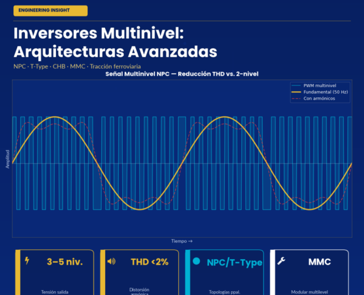
The four structural advantages of MLI. (1) Divided blocking voltage — each semiconductor blocks only V/(m−1). (2) Reduced THD without sacrificing power — stepped waveform drops below 5% THD with no filter, complying with IEEE 519 directly. (3) Lower dv/dt — transitions occur between adjacent levels, reducing motor insulation stress by orders of magnitude. (4) High efficiency — semiconductors switch at low frequencies; overall efficiency approaches 98% in megawatt applications.
The Fundamental Principle — Additive Voltage Synthesis
A conventional two-level inverter has two possible output states per phase: +V/2 and −V/2. The transition between them is abrupt and requires a high switching frequency and a bulky output filter to approximate a sinusoid. Each switch must block the full DC-bus voltage, imposing a hard limit: above roughly 1700 V of bus, commercial IGBTs start running short on margin; above 3.3 kV, they simply do not exist as a single part.
The multilevel inverter solves this with an additive synthesis strategy: the output voltage is constructed by summing smaller contributions from intermediate DC-bus levels or independent sources. The resulting staircase waveform naturally approximates a sinusoid without high-frequency switching. The structural cost: more components than a two-level inverter — more switches, isolated gate drivers, clamping elements. Topology selection is the consequence of systematically analysing when that cost is justified.
The Three Classical Topologies
NPC — Neutral Point Clamped
Introduced by Nabae, Takahashi and Akagi in 1981, the NPC divides the DC bus into (m−1) levels through series capacitors and uses clamping diodes to connect intermediate nodes to switching points. The DC bus is single and shared by all three phases, minimising total capacitance. The main limitation is voltage imbalance in the intermediate DC-bus capacitors — manageable at m=3, but for m≥5 the control complexity becomes prohibitive. Practically all commercial NPC products are limited to three levels.
| Aspect | Characteristic (m-level NPC) | Design Implication |
|---|---|---|
| Active switches | 2(m−1) per phase | Linear growth with m |
| Clamping diodes | (m−1)(m−2) per phase | Quadratic — limits practical m to 3 |
| DC sources | 1 (single bus) | Architectural advantage over CHB |
| Dominant application | Three levels (m=3) | STATCOM/SVC, drives 690 V–4.16 kV, grid-tied PV |
FC — Flying Capacitor
Proposed by Meynard and Foch in 1992, the FC replaces clamping diodes with floating capacitors holding intermediate voltages. Every switch blocks the same voltage, and redundancy of switching states allows active capacitor balancing through appropriate state selection each switching period — more manageable than the NPC. The disadvantage is quadratic capacitor growth (a 5-level FC requires 6 floating capacitors per phase) and a complex pre-charge startup routine. The FC dominates high-speed railway traction where per-cell modularity justifies the cost.
CHB — Cascaded H-Bridge
The CHB series-connects multiple complete single-phase H-bridges, each fed by an independent isolated DC source. The output voltage is the algebraic sum of each cell’s contribution. A CHB with N cells per phase produces 2N+1 levels. Its three structural advantages — pure modularity, absence of inter-capacitor balance issues, fault tolerance through cell bypass — make it the preferred topology when the application provides separate DC sources naturally (batteries, PV strings, multi-pulse transformers). Without that condition, NPC or FC are preferable.
| Topology | Key Components | Main Advantage | Main Disadvantage |
|---|---|---|---|
| NPC | 2(m−1) IGBTs + (m−1)(m−2) diodes | Single shared DC bus | Capacitor imbalance limits to m=3 |
| FC | 2(m−1) IGBTs + (m−1)(m−2)/2 cap. | Natural balance via redundant states | Quadratic capacitors; complex pre-charge |
| CHB | 2(m−1) IGBTs + (m−1)/2 isolated sources | Pure modularity, fault tolerance | Needs isolated DC sources or multi-pulse transformer |
Modulation Strategies
Multi-Carrier SPWM and Phase-Shifted PWM (PS-PWM)
The natural extension of classical SPWM uses (m−1) triangular carriers per the Phase Disposition (PD), Phase Opposition Disposition (POD), or Alternative POD variants. PD minimises line-voltage THD and is preferred for NPC; POD minimises current THD. PS-PWM is specific to the CHB: each H-cell uses its own carrier, shifted 360°/N relative to the next, effectively multiplying the apparent output switching frequency by N without any individual switch switching faster — enabling very high efficiency at megawatt scale.
Selective Harmonic Elimination (SHE-PWM)
For very-high-power applications where switching losses dominate, SHE-PWM precomputes offline the switching angles that cancel specific harmonics (5th, 7th, 11th, 13th). For N pulses per quarter cycle, exactly N−1 harmonics can be eliminated. Switching losses drop to approximately 1% versus 3–4% for conventional PWM. The limitation is slow transient response and numerical instability beyond 5 levels.
Space Vector Modulation (SVM)
SVM operates on the αβ space of three-phase output voltages. Each switch-state combination corresponds to a vector, and the reference is synthesised as a linear combination of adjacent vectors. For a 3-level inverter: 27 vectors. For 5 levels: 125. For 7 levels: 343. Algorithmic complexity scales with m but SVM offers optimisable THD and high dynamic performance, making it the preferred strategy for FACTS and high-performance drives.
The Current Frontier — RDC-MLI and Asymmetric Topologies
Classical topologies share a scaling problem: switches grow with levels (a 7-level MLI requires 12 switches per phase; a 21-level one, 40). For 30-year reliability commitments, this escalation becomes unacceptable. Two research directions address it:
RDC-MLI (Reduced Device Count) architectures split the inverter into a level-generation stage (high frequency, determines magnitude) and a polarity-generation stage (fundamental frequency, decides sign). This separation reduces switching losses significantly. RDC-MLIs achieve 7 levels with 8–10 switches versus 12 for classical NPC/FC.
The asymmetric exponential trick. If CHB cells produce voltages in binary geometric progression (Vdc, 2·Vdc, 4·Vdc, 8·Vdc), a 4-cell inverter produces 31 levels instead of the symmetric 9 — with the same switch count. Ternary asymmetry (powers of 3) maximises level density (3N theoretical levels) at the cost of control complexity. The trade-off: cells are no longer interchangeable, losing the classical CHB’s pure modularity.
Applications — Where MLI Is the Mandatory Solution
Railway Traction
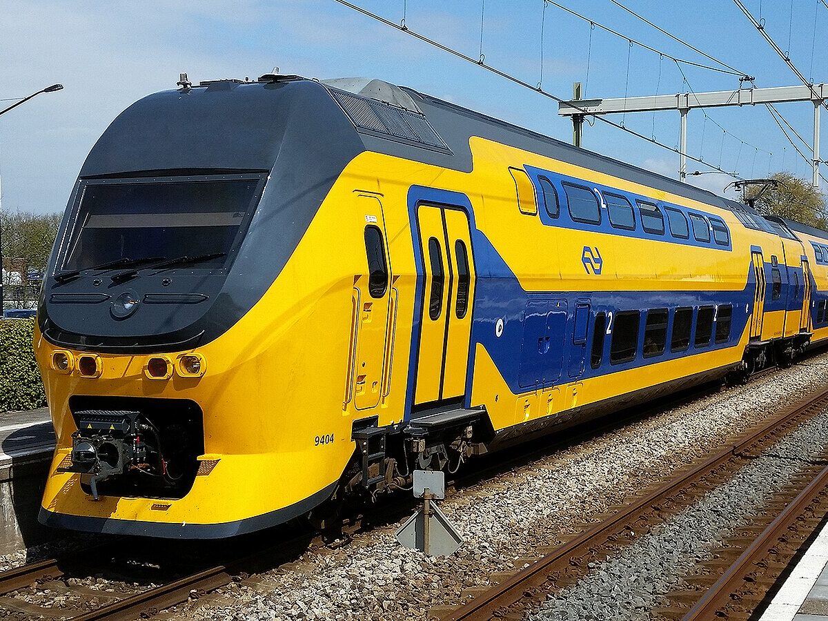
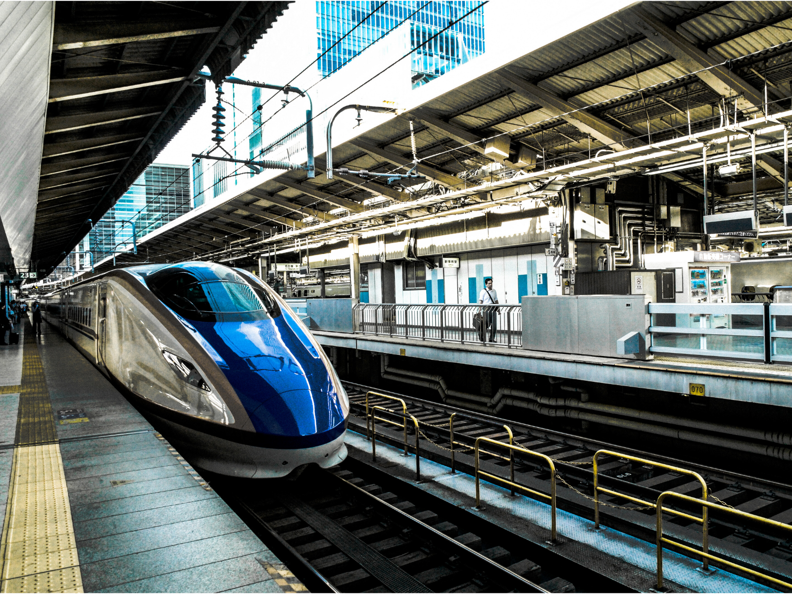
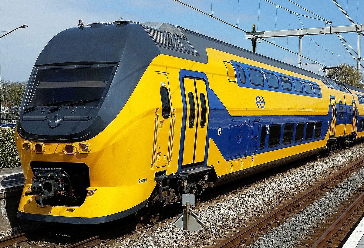
High-speed traction (Talgo, Stadler, ICE) uses DC buses of 3 kV or 1.5 kV fed from the catenary, driving megawatt-scale motors. The three-level NPC has dominated this segment since the 1990s. The transition to SiC in some recent designs reopens the two-level debate — SiC allows faster switching without loss penalty — but the topology decision remains application-specific.
FACTS — STATCOM and SVC
A modern 100 MVAr substation STATCOM can have hundreds of H-cells per phase, each switching at a few hundred Hz, summing output voltages up to 33 kV without a step-up transformer. CHB modularity fits perfectly with qualified replicated H-cell manufacturing, and bypass fault tolerance keeps operation running with degraded performance — exactly what transmission operators require.
HVDC and Transmission
Modern VSC-HVDC uses the MMC (Modular Multilevel Converter) — an advanced CHB variant with hundreds of submodules per arm. European inter-country submarine interconnections (NorNed, Cobra Cable, Viking Link) use MMC with several hundred levels, achieving THD below 1% directly at the connection point. Cell redundancy makes per-cell failure irrelevant: with 400 cells per arm, the system tolerates dozens of failures without service loss.
Large-Scale Renewables and EV
PV plants use CHB naturally (each H-cell fed by a panel string); wind farms use three-level NPC for back-to-back converters; offshore wind increasingly uses MMC via HVDC. In automotive, the transition to 800 V battery buses in premium EVs (Porsche Taycan, Audi e-tron GT, Hyundai Ioniq 5/6) makes three-level inverters with 600–650 V SiC devices an increasingly attractive alternative to single-level designs with tight voltage margin.
Diagnosis and Troubleshooting
| Observed Symptom | Probable Cause | Corrective Action |
|---|---|---|
| NPC capacitor imbalance | Deficient neutral-point control | Implement active control via redundant state selection |
| High THD at low modulation | Modulation index M < 0.5 in SPWM | Switch to SHE-PWM or third-harmonic injection |
| FC capacitor overvoltage | Active balance algorithm failure | Review redundant state selection; verify pre-charge |
| CHB cell current imbalance | Different battery SOC or DC sources | Adaptive asymmetric modulation to redistribute power |
| Elevated common-mode spikes | Modulation breaks 3-phase symmetry | Select PD-SPWM if NPC; review switching sequence |
| Saturated transient response (SHE) | Precomputed table out of regime | Hybrid SHE + SPWM in transients; revert to SHE in steady state |
Topology Selection Matrix
| Design Question | Favours NPC | Favours CHB |
|---|---|---|
| Single shared DC bus? | Yes — native to NPC | No — CHB needs isolated sources |
| Application provides separate DC sources? | No | Yes — batteries, panels, multi-pulse transformer |
| Levels required? | Up to 3 | 5 or more |
| Fault tolerance via cell bypass critical? | No | Yes |
| LRU maintenance modularity important? | Less | Yes — identical replaceable cells |
The closing argument. Multilevel inverters are not an emerging technology — they have been the consolidated solution for medium-voltage, high-power power electronics for three decades. What continues evolving are the variants: three-level NPC consolidated, MMC dominating HVDC, RDC-MLI and asymmetrics as an active research frontier, SiC reopening the topology debate in the medium-power range. Topology selection is not a matter of taste: it is the consequence of a systematic analysis of bus voltage, waveform quality, DC source availability, modularity criticality, and maintainability horizon. Premium SA applies this analysis at the D2W gate of every new programme — because the right topology, well-chosen modulation, and rigorous thermal control are what differentiates a megawatt converter that meets 30 years of service from one that fails at five.
This article was originally published by Premium PSU.