Built to Spec—Olympus Delivers on Customised Sensor Solutions
We’ve been designing and customising sensors for decades to create solutions that meet our customers’ unique requirements. Today, we’ve developed capabilities that allow for onsite application testing of newly designed sensors to ensure that our solutions meet our customers’ needs.
Sensor design is highly specialised, often supporting sensitive commercial and military inspections that require confidentiality and expert staff. Our team of sensor design experts includes product specialists who develop and solve applications as well as development engineers who have over 100 years of combined experience in sensors.
Our team specialises in developing solutions using advanced technologies—conventional ultrasound (UT), phased array (PA) ultrasound, eddy current (EC), and bond testing. We support customers in all industries, including power generation, oil and gas, transportation (automobile, rail, aerospace), and manufacturing.
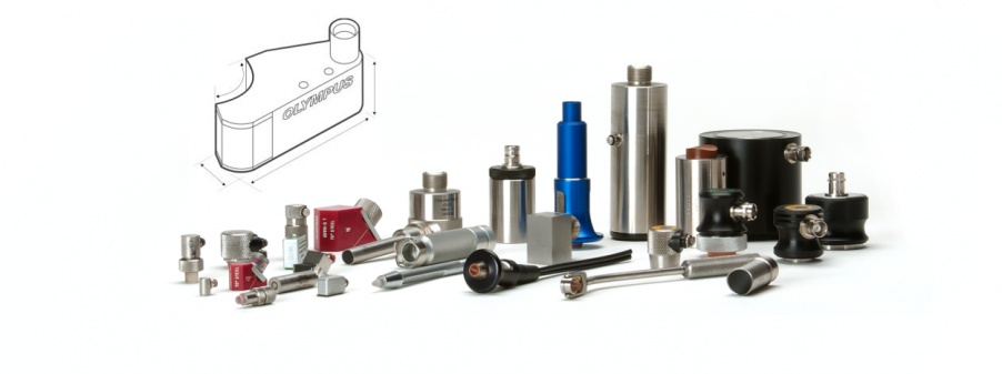
To date, our team has developed and manufactured 25,000 custom sensor designs using a variety of advanced tools, such as:
- CNC lathe machinery
- 3D printing/additive manufacturing
- A FaroArm® coordinate measurement tool
- CIVA NDT simulation software
- And, of course, our full line of flaw detectors and bond testers
How We Solve Complex Application Challenges
Customers typically approach us for a custom solution after they’ve tried off-the-shelf options that did not deliver the desired results. They need help overcoming limitations such as space and size constraints, complex part geometries, difficult-to-inspect materials, short inspection cycle times, and stricter imaging/sizing requirements.
A custom project begins when a customer sends us a request outlining the problem. If needed, we’ll ask the customer to send us test samples with defect information to help us in the development process. Our experts will first conduct extensive testing with existing technology on these samples to understand what’s necessary to solve the application. Next, they’ll work with the customer to develop a solution within the constraints of their inspection requirements. This includes recommending the appropriate probe, tooling, scanner and/or instrument and, potentially, a custom developed solution. The customer will receive a test report and a follow up in-person (or virtual) visit.
Dealing with the Challenges of COVID-19
We’ve implemented live virtual demonstrations of our solutions as part of our COVID-19 response. We plan to continue to offer this service for the convenience of our customers, who can also get a live intro to our instruments and even watch parts being inspected using common sharing platforms (Microsoft Teams, Skype for Business, WebEx, and TeamViewer). Because we know security is important, we are offering a special Transmission Control Protocol (TCP) account to handle International Traffic in Arms Regulations (ITAR) information; this includes an encrypted email and Microsoft solutions to collaborate securely with customers.
From Custom to Common—Challenge-Driven Innovation
Did you know that our off-the-shelf flexible phased array probe began as a custom solution? While they’re now commonly used to inspect pipe elbows, the motivation behind their development was a customer who needed a phased array sensor that could conform to varying geometries on carbon fibre reinforced polymer (CFRP) aerospace components.
Solving the Problem of Complex Geometries
It’s challenging to perform high-resolution ultrasonic inspection of complex shapes with changing geometries. To inspect such components using conventional ultrasonic probes, they must be held perpendicular to the surface at every point of data acquisition. This inspection process is slower, and it’s easy to miss defects between acquisition points. Phased array ultrasonic testing (PAUT) technology allows high resolution rapid scanning of large areas, but conventional phased array probes are rigid and cannot conform to changes in component geometry.
This inspection is improved and simplified using a flexible array probe that conforms to changing geometries so the elements remain perpendicular to the surface throughout the inspection. This unique feature reduces the need for complex scan plans, increases the coverage of each scan, simplifies the data interpretation, and reduces the equipment requirements to complete an inspection.
Innovating a New Probe
An initial investigation was performed to validate the current ultrasonic techniques used for radius inspection of CFRP parts, including single-element transducers (UT) and curved phased array (PA) immersion probes. Testing was completed using a CFRP standard with two flat portions and one 25 mm radius.
Step 1: Validating the Current Ultrasound Inspection Methodology
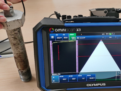
Figure 1 shows the UT probe coupled to the radius and oriented perpendicular to the inside radius to observe the back wall. Note that the inspection is very sensitive to orientation, and the known flaws could be easily missed by an inexperienced user.
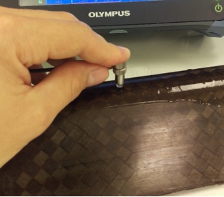
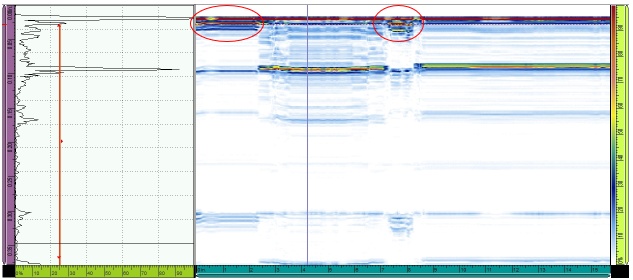
Figure 2 shows the probe’s A-scan and B-scan, which was encoded over the length of the part. Two flaws were detected (circled in red), where the loss of back wall reflection and the reflector appear closer in time.
Step Two: Validating the Curved Phased Array Probe Inspection Methodology
Testing with the curved immersion phased array probe involved a more complicated setup and data acquisition. A probe holder was required to mechanically position the array at a specific water path and orientation to the radius. Figure 3 shows the setup before being immersed in a water tank.
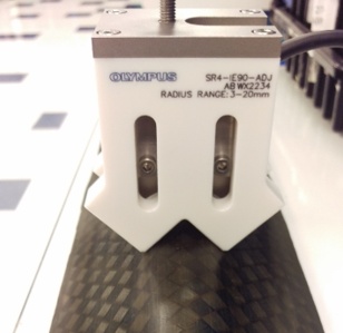
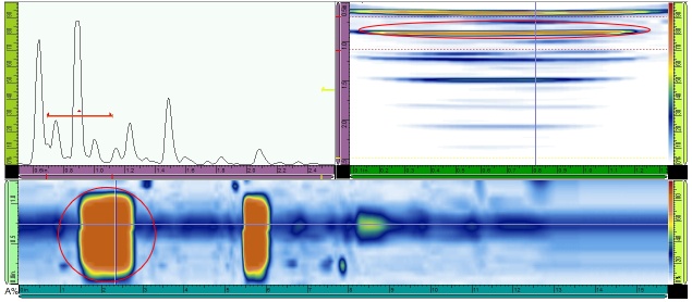
Figure 4 shows the A-scan, B-scan, and C-scan acquired using the concave curved probe. The difficulties during test setup included choosing the water path, detecting the back wall reflection, and flaw sizing. In the B-scan, the 12.7 mm (0.5-inch) reflector is stretched depending on the water path and virtual aperture (number of elements) chosen. The coverage area also changes significantly with the water path, focal depth, and aperture size.
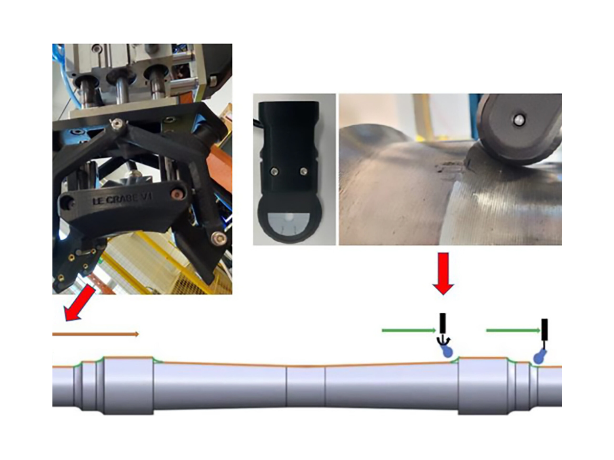
The Custom Solution—A Flexible Array Probe
As illustrated above, when geometries get complex, a very small probe must be used to inspect each small portion of CFRP at a time. Based on the investigation results using conventional UT and curved phased array inspection methods, the team designed and created a flexible array probe to provide a quick way to image curved areas.
Step Three: Testing the Flexible Probe Design’s Durability
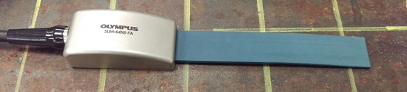
Before inspecting CFRP parts with the flexible phased array probe, it was tested to verify its concave and convex flex limitations. In each test, the probe was flexed around a part with a known diameter and then checked to ensure the probe was not damaged. Figure 5 illustrates the probe flexed concave around a 12.7 mm (0.5-inch) diameter gauge without causing damage.
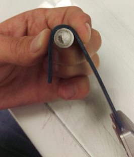
Figure 6 shows the array flexed convex (elements facing outward) around a 40 mm (1.6-inch) diameter gauge without damage to the probe.
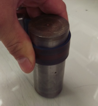
These tests enabled the engineers to determine the limitations for safe use of the flexible array. Flexing the array further caused individual elements to lose sensitivity and tearing of the tongue material.
Step Four: Testing the Flexible Array’s Inspection Results
The flex durability testing proved that the probe could be used in its concave flexed position on the outside diameter of the CFRP part’s 25 mm radius. Figure 7 shows the setup to inspect the CFRP part with the flexible array held in contact with the 25 mm radius.
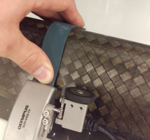
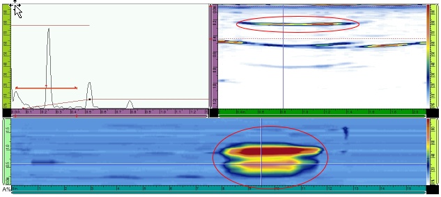
Figure 8 shows the A-scan, B-scan, and C-scan acoustic data acquired with the flexible array probe. Benefits of this inspection included full coverage of the radius, accurate flaw measurements, and a simple mechanical setup. In the B-scan, the results for the 12.7 mm (0.5-inch) reflector were only slightly over the actual measurement (15.9 mm (0.627 inches)), which was much more accurate than the concave immersion probe. The coverage area was much larger, and the data was easier to understand since the results included a portion of the first flat face, through the radius, and into the second flat portion of the part.
Flexibility Beyond CFRP Inspection
Our evaluation of the three inspection methods (single-element UT, curved immersion PA probe, and our flexible array probe) determined that the flexible array was the easiest to implement and provided the most accurate data. The flexible array is practical for low-volume contact inspection using almost any Olympus flaw detector.
We quickly recognised the advantages the probe offered in other applications, such as inspecting pipe elbows. The probe’s ability to generate C-scan data can help users rapidly quantify the effects of corrosion within an area, potentially saving customers time and money.
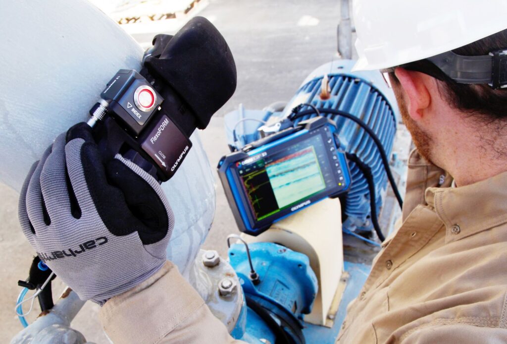
The result is the FlexoFORM™ scanner, which uses a flexible array probe to perform corrosion inspection on pipe elbows. The solution incorporates a 64-element, 7.5 MHz, 1 mm pitch flexible probe with a 7 mm elevation that is positioned in a water wedge. The water wedge enables excellent coupling on complex shapes and helps protect the probe. It has proven to be a fast, cost-effective pipe elbow inspection solution.
For the moment, these are the only flexible array solutions in our product line, but the possibilities for CFRP, plastics such as high-density polyethylene (HDPE), and other parts that have complex geometries make this a good consideration for further development.
To consult the experts in our sensor design team about your special application, start by filling out the Custom Phased Array Probe and Wedge Design Inquiry form or contacting us directly.
This article was originally published by Olympus.