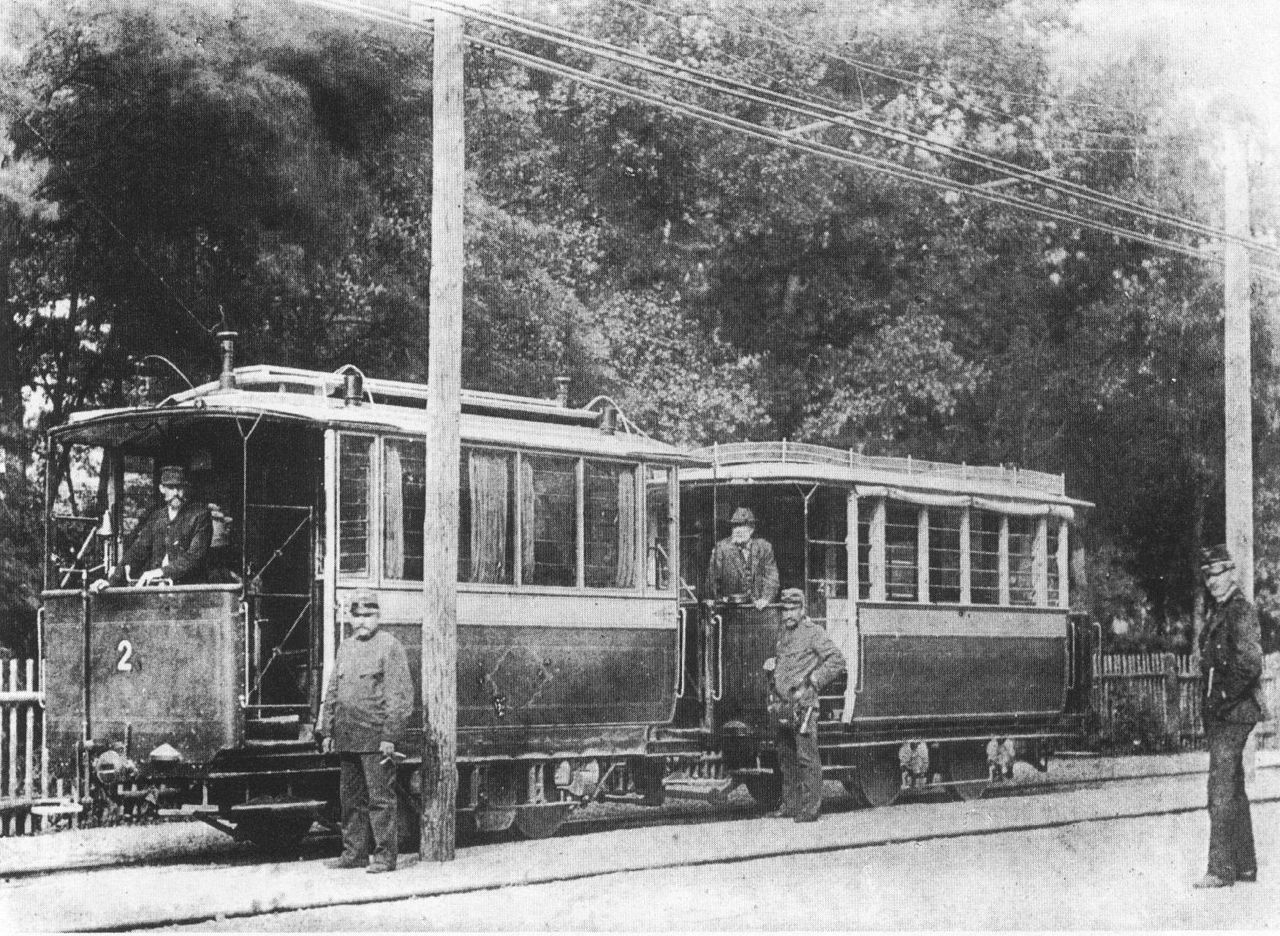
Rail Innovation Timeline – 1900s
Viper Innovations’ CableGuardian system is one of the latest in a long line of achievements in railway technology targeted at improving the safety of the railway for the public and workforce and increasing the efficient operation of the railway-at-large. To celebrate these past innovations and all things to do with the improvement of safety and efficiency, we researched some key points in time that moved the railway forward. This piece covers those during the 1900s, from Hermann Lemp’s Diesel-Electric Traction in 1914 to the Train Protection and Warning System (TPWS) in 1997. Click to read our earlier rail timeline article which focuses on the 1800s; outlining notable innovations during this period.
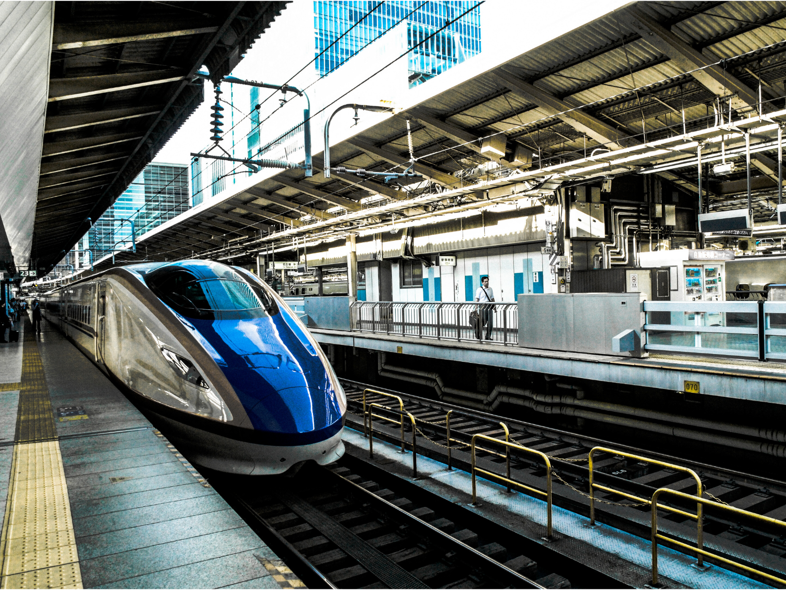
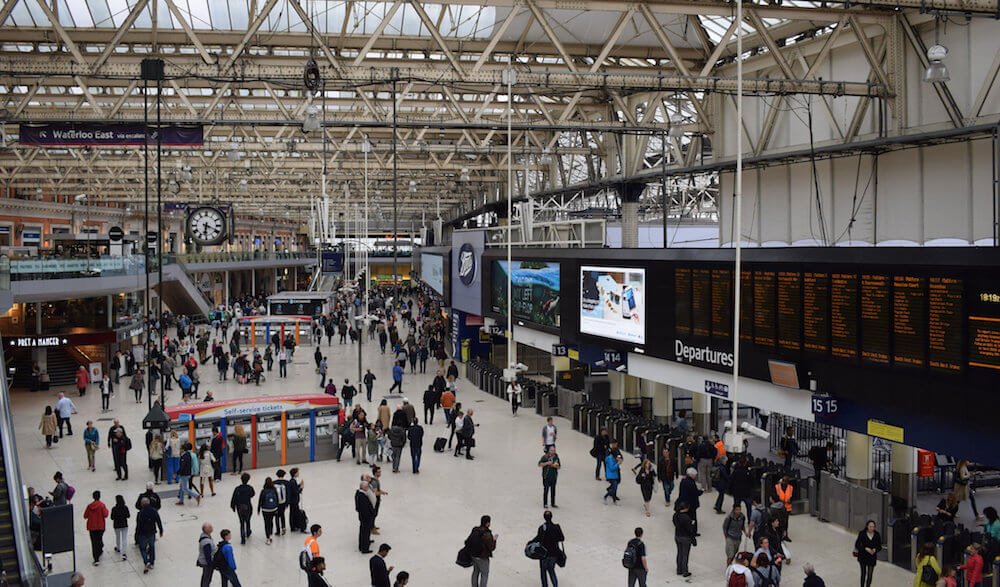
The 20th century gave birth to new types of traction, significant increases in safety and efficiency in train operations and maintenance, new materials and methods and the introduction of greater centralisation in command and control. The incremental use of first electrical and then electronic means of controlling trains enabled faster and more dense services, serving more people and moving more goods, which was essential during the war years. The development of high-speed rail, firstly in Japan with the Shinkansen, or Bullet Train, required innovation in maintenance practices to ensure it would keep up with service requirements whilst the increase in road traffic across the century gave renewed focus on the road/rail interface with level crossing technology. The continued push for the highest possible safety combined with efficient operations required to compete with road traffic provided significant developments in operational safety, which provided the springboard for the developments that would be used to join Europe’s rail network in the next century.
- 1914 – Diesel-Electric Traction – Hermann Lemp
General Electric electrical engineering developed and patented a reliable direct current electrical control system combined with a diesel-powered generator to drive a DC machine. Lemp’s design used a single lever to control both engine and generator in a coordinated fashion and was the prototype for all diesel–electric locomotive control systems. The first applications were for shunting engines.
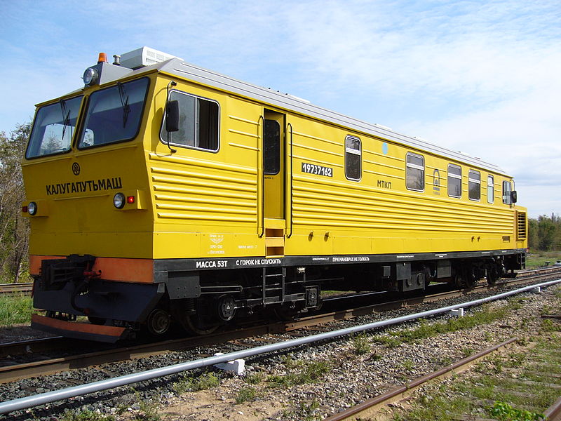
- 1925 – Track Geometry Train – Emile Hallade
Track geometry cars started to emerge in the 1920s when rail traffic became sufficiently dense that manual and visual inspections were no longer practical, the driver for many other automated monitoring systems. The increasing speeds of trains of that era required more meticulously maintained tracks. In 1925, the Chemins de fer de l’Est put a unit into operation carrying an accelerograph developed by Emile Hallade, the inventor of the Hallade method of setting out track curves. The accelerograph could record horizontal and vertical movement as well as roll. It was fitted with a manual button to record milestones and stations in the record.
- 1937 – Route Relay Interlocking and NX Route Setting – General Railway Signal Company
The transition from a fully mechanical interlocking, through electro-mechanical to fully electrical interlocking took place in the US around 1929 and was installed at Lincoln, Nebraska on the Chicago, Burlington, and Quincy Railroad. This development paved the way for a greater level of control and automation of larger sections of track that created Centralised Traffic Control systems, the first of which was the Entrance-Exit (NX) Signalling System, first deployed at Brunswick on the Merseyrail network in Liverpool in 1937. The NX system uses a mimic of the railway and breaks the railway into controlled signals and auto-sections, with a controlled signal at a junction or other critical piece of infrastructure. The signaller presses a button to ‘call’ the route at the desired entrance signal and presses the corresponding exit signal required. The relay logic then sets the points and track circuits detect the position of trains. When the logic proves that the route is set, locked, and detected, and the route ahead clear, a proceed aspect will be shown to the driver of the train to provide movement authority. These systems are located in larger Power Signal Boxes, with a much larger concentration of the railway controlled from a centralised point, greatly increasing the efficiency of the signalling control and allowing greater throughput of trains.
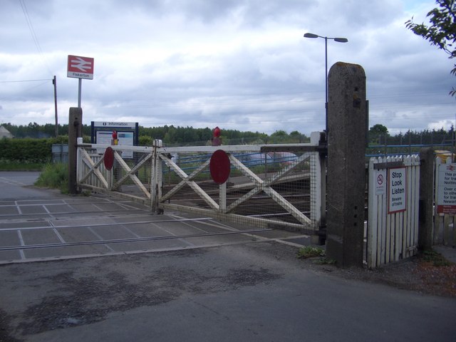
- 1952 – Manually Controlled Barrier Level Crossing
As traffic became faster on the railway and road traffic more dense, improved means of protection of the intersection between road and rail was required. An MCB crossing is controlled by an adjacent signal box where the signaller can see the road closure and determine that the crossing is not obstructed before signalling the train to proceed. Normally an MCB crossing either has two full road width barriers or four half road width barriers that fully close the road. This type of crossing is also often provided with standard road-lights and alarms that operate when closing. The first crossing of this type was tested at Warthill, North Yorkshire in 1952.
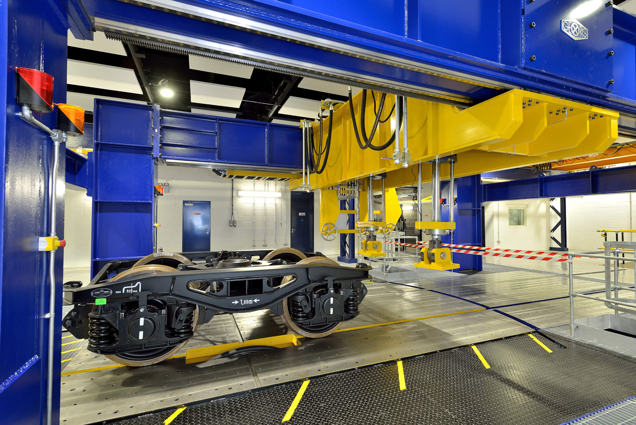
- 1959 – Continuous Welded Rail (CWR)
Although in use in various other administrations, the British Railway adopted continuous welded rail track as a standard in 1959 following lengthy technical investigations. The adopted track form was designed for the national temperature range and the humid and generally corrosive atmosphere found in the UK. Apart from the more comfortable ride for passengers, the advantages of using CWR included economic ones, such as an extension of rail life by between 30 per cent and 40 per cent, savings in the cost of track maintenance, extended sleeper life, and reduction in fuel costs and wear and tear on rolling stock. Additionally, the important gain in safety resulting from the elimination of rail joints. CWR needs to be ‘stressed’ when installed, which means to draw it to a tension that mimics 27 degrees Celsius, and lengths of track welded using flash-butt or aluminothermic welding
View the full timeline of the 1900s here.
We hope you’ve enjoyed reviewing our collation of interesting rail innovations. Although we have focussed on innovations that appealed to us as innovators in safety and efficiency, there are countless others that could have qualified. It’s important to recognise that missing from the innovations listed is the people who made it happen as part of the wider team. An individual may have a spark of brilliance to light the way, but it takes teams of people to turn an idea into an innovation. In the modern, safety critical and densely populated rail networks of today, bringing an invention to life, enabling its progress, assuring its safety, refining its operation, and keeping it in use throughout its lifecycle is a tremendously difficult task. Viper has always recognised the vital part played by our clients’ engineers, specifiers, enablers, assurance, users, sponsors, and look forward to many more fruitful collaborations in the years ahead.