Premium Power Supplies
Control Loop Stability Measurement in Power Supplies
Introduction
Switched Mode Power Supplies (SMPS) use control loops to ensure that the working point is obtained with the minimum steady state error and fast transient response. To achieve these objectives, a strong control action is needed. But if this action is too aggressive, it can make the system unstable, leading to oscillations that can increase ripples, component stress or even damage the converter or loads.
The control action can be estimated with linear control calculation techniques. Even though SMPS are nonlinear, time-varying systems due to the switching actions can be modeled with an averaged small-signal linearized model.
Stability of Power Converters
The stability analysis of SMPS is usually tackled by using their averaged models, where resulting no linear models are linearized around the operating point. The averaged model of the control loop of any power converter can be described as:

Where H(s) is the plant to control, C(s) is the compensator, and K(s) is the dynamics ́ feedback. As a result, we can describe the system gain with the following equations, where T(s) is the loop gain:

The control loop ́s goal is that the measured output M(s) follows the reference R(s). To achieve it, the gain M(s)/R(s) must be close to 1, which happens when the loop gain T(s) is very high.
What Happens If T(s) Is Close to -1?
In this case, the denominator 1 + T(s) is close to 0 and the gain of the system is approaching to infinite. This leads to instability, causing the system to saturate or oscillate.
If we want to analyze the stability of the system, we need to verify how close T(s) can be to -1, meaning when the loop gain is 1 (0 dB) and the loop phase is -180o. A bode plot, as the one shown in Figure 1, is a useful tool to do that.
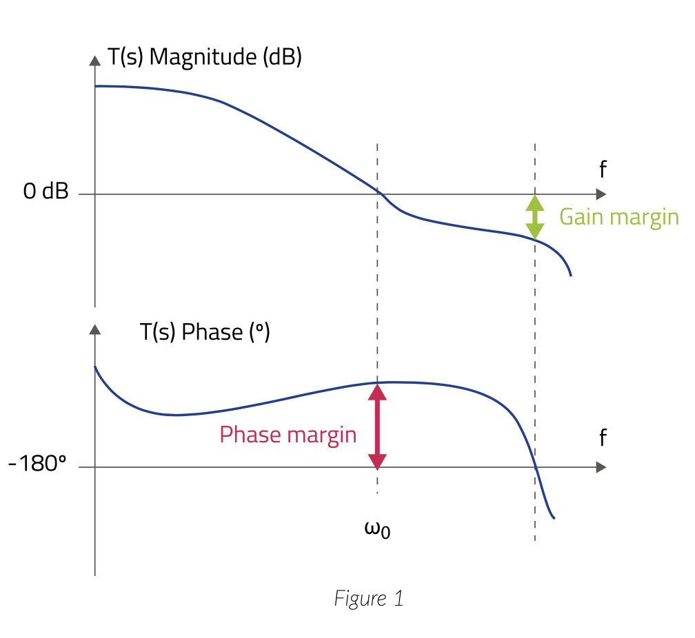
The phase margin is the difference between -180o and the phase at 0 is the crossover point (at 0 dB) of T(s) magnitude. That is the system ́s phase margin before becoming unstable.
